Appropriate alignment of the multifocal optics with a patient’s visual axis is a critical—yet often overlooked—component of successful soft multifocal contact lens fittings. For our purposes, the visual axis is defined as the line that connects the fovea with the fixation point. When there is a misalignment between the center of the multifocal optics and the patient’s visual axis, it can result in poor visual acuity, induced aberrations, and subjective complaints of glare, shadows, 3-D effects, and halos.
Unfortunately, the conventional method of fitting multifocal lenses over the center of the cornea does not always ensure appropriate alignment of the multifocal optics over the visual axis. Dr. Matthew Lampa et al. began studying this issue by re-purposing the corneal topographer to measure the surface profile of four commercially available brands of soft, simultaneous-designed, multifocal contact lenses. With a detailed evaluation of the topography maps taken over the multifocal contact lenses, he discovered that the lenses’ optical zones were consistently displaced temporal to the visual axis.1 The amount of misalignment across 18 subjects ranged from 0 to 1.25mm in the temporal direction. Dr. Lampa’s results were similar to our SpecialEyes 54 Multifocal studies, which found an average misalignment of .78mm in the temporal direction across 63 eyes.2
Misalignment between the multifocal optics and visual axis can occur due to a variety or combination of factors. These factors include the temporal displacement of the lens (due to scleral shape), the nasal decentration of the pupil, and/or a temporally displaced fovea. Regardless of the cause, this misalignment will alter the way light enters the eye and can ultimately lead to unhappy multifocal patients with unsuccessful lens fittings that should otherwise be a slam-dunk success.
At SpecialEyes, we believe that all presbyopic patients should have the ability to wear multifocal contact lenses if they so desire. With this in mind, SpecialEyes is now offering the 54 Multifocal with OptiSync® Technology. OptiSync® Technology offsets the multifocal optics from the center of the lens and targets alignment with the patient’s visual axis. By coupling this technology with our fully custom, pupil-optimized, 54 Multifocal design, you now have the power to give struggling multifocal patients what they’ve always wanted: freedom from glasses.
This post will cover techniques for predicting/identifying a potential misalignment issue so that you know when to utilize OptiSync® Technology.
Method #1: Over-Topography
One method to evaluate a misalignment between the center of the multifocal optics and a patient’s visual axis is to compare topography of the bare cornea to topography taken over the top of the multifocal contact lens. To accomplish this, you need to use the topographer’s “difference display” map setting, also known as subtractive or comparative maps. This topographer functionality subtracts the map taken over the top of the contact lens from the baseline map of the patient’s bare cornea to provide a clear view of the multifocal optics. Let’s walk through the step-by-step instructions:
- Perform baseline topography of the bare cornea.
- Place a pair of soft multifocal contact lenses on the eyes. If you are using an in-office multifocal design, we recommend using a lens with a high add power. This will enhance the appearance of the center of the optics when viewing the topography results.
- After allowing a few minutes for the lenses to settle, utilize your slit lamp to ensure proper centration and on-eye lens performance. If the lenses fit well, you may proceed with the next step. If not, you must address the fit issue first.
- Perform corneal topography over the top of the soft multifocal contact lenses. Instruct the patient to focus directly on the fixation target within the instrument, as this will ensure that the center of the map will represent the patient’s visual axis.
- Next, display the maps in tangential power. Depending on the topographer make and model, this may be a function termed as “tangential,” “curvature,” or “instantaneous.”
- Locate the topographer’s difference display or subtractive/comparative map function. Depending on the make and model of the topographer, this function may appear as an icon that looks like three topographic maps on the same button or a dropdown menu option titled “Diff,” “Refractive Compare,” or “Power Difference.” Select the baseline map first and then the map taken over the contact lens (both in tangential power) to produce a third map known as the “tangential power difference” map. Once the difference map function has been deployed, a difference/comparative/subtractive map will be automatically generated adjacent to the two original maps.
- If needed, highlight or enhance the power profile across the optic zone of the contact lens by adjusting the color display scale on the difference map.
- Measure the difference between the patient’s visual axis (center of map) and the center of the multifocal optics by using the topographer’s measuring tool (white cross, ruler, etc.). If there is .50mm or more of misalignment, the patient will likely experience improved vision with OptiSync® Technology (offset optics).
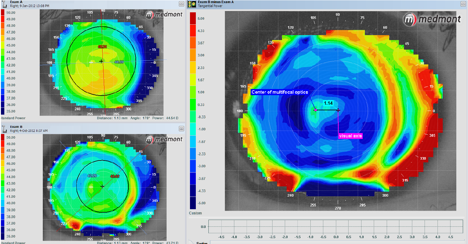
The example shown in Image 1 is the result of following the step-by-step instructions above. The upper-left image is the baseline map taken of the bare right cornea, and the lower-left image is the map taken over the right contact lens. The larger map to the right is the subtractive/comparative map, also known as the difference display map. As long as the patient is fixated down the axis of the instrument, the center of the map represents the patient’s visual axis. By using the ruler to measure the distance between the center of the map and the center of the multifocal optics, you can determine the amount of misalignment. In the example below, there is approximately 1.14mm of misalignment between the center of the multifocal optics and the visual axis.

Image 1. Topography of right eye
By subtracting the map taken over the top of the contact lens from the baseline map of the bare cornea, we can easily see the center of the multifocal optics. While it is possible to assess misalignment by simply performing topography over the lens, it can be more challenging to see the center of the optics in relation to the visual axis. If you choose to skip the baseline topography step, you may need to adjust the color display scale until the center of the optics becomes clearer. The scaling will vary by the power of the lens ordered, so you may have to experiment with the different scale steps. For specific instructions on how to perform these functions, refer to the topographer’s user manual or contact the manufacturer.
Method #2: Examine Angle Kappa Values
Much of what we know about the concepts of optical alignment comes from ophthalmology literature. In a variety of studies, research has demonstrated that centering laser-ablation treatment zones over the center of the pupil can be problematic for patients who have a large discrepancy between the center of the pupil and the visual axis or large angle kappa.3, 4 Additionally, a large angle kappa can contribute to unwanted vision issues with multifocal intraocular lens (IOL) implants.3–5 Angle kappa is technically defined as the angular distance between the visual axis and pupillary axis, while angle lambda is the angular distance between the line of sight and pupillary axis. The terms “angle kappa” and “angle lambda” tend to be used interchangeably because they are nearly identical as long as the fixation point is not close to the eye. 3, 4
Refractive surgeons have approached this issue by using the corneal light reflex or corneal vertex as a way to estimate the location of the visual axis.6 For patients with a large angle kappa, aligning the laser-ablation treatment zones closer to the visual axis has been shown to improve outcomes, resulting in less induced ocular aberrations and a reduction in halos and glare.3–6 Taking what we have learned from the ophthalmology world, you can predict a potential multifocal misalignment by examining a patient’s angle kappa value. Some topographers and wavefront aberrometers automatically calculate this measurement, while others can estimate angle kappa by measuring the distance between the corneal vertex and pupil center (using X-Y Cartesian coordinates).3
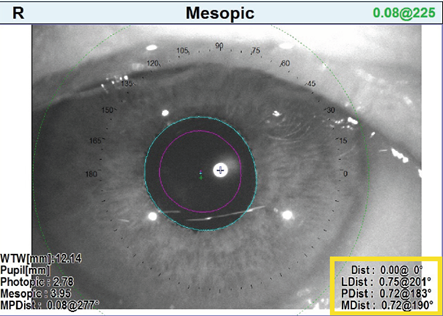
Image 2. Angle Kappa measurements taken with the Marco/Nidek OPD-Scan III
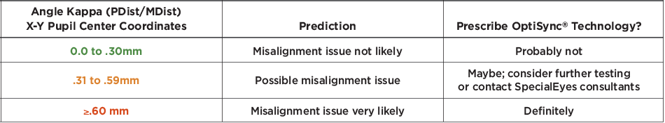
As an example, the Marco/NIDEK OPD-Scan III has both corneal topography and wavefront capabilities that can be used to evaluate the distance between the pupillary center and visual axis. This device aligns itself for topographic and wavefront measurements by finding the longest light ray (the optical axis), which is used to estimate the location of the visual axis. According to the NIDEK OPD-Scan III Operator’s Manual, the device then automatically calculates the distance and angle from the alignment light to the pupil center in both photopic and mesopic conditions (Image 2). These values are displayed on the map as PDist (small pink cross) and MDist (small blue cross), respectively. According to Dr. Timothy Petito, 100% of patients who have >.70mm PDist or MDist value will fail in a multifocal contact lens due to a large angle kappa that correlates to a misalignment between the center of the multifocal optics and the visual axis. By combining Dr. Petito’s clinical experience with the OPD-Scan III and the literature on refractive surgery and multifocal IOLs, we have created the following guidelines for predicting a multifocal contact lens misalignment issue from angle kappa values:

New information and the additional capabilities of some integrated wavefront aberrometers are poised to make the determination of when to use OptiSync® Technology even quicker and more predictive. The OPD Scan III integrated wavefront aberrometer can calculate angle alpha, which is the difference between the geometric center of the limbus (the anatomic center of the cornea) and the optical axis. This value is shown on the map as LDist and displayed as a small green cross. Most of the time, lenses tend to center at or near the center of the cornea. The closer the center of the cornea (and the center of the lens) is to the optical axis, the more symmetric the combined power distribution is around the optical axis. The further the center of the lens is from the optical axis, the more asymmetric the combined power distribution is around the optical axis. It is this asymmetric power distribution around the optical axis that creates higher-order aberrations, particularly coma, which results in unwanted visual symptoms.
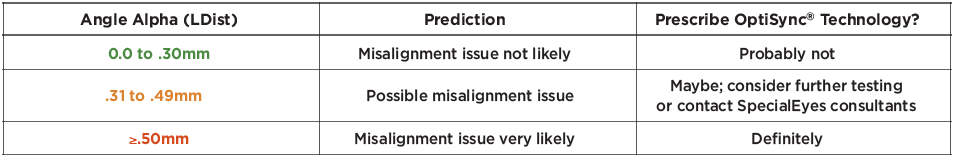
Similar to his clinical experience in evaluating angle kappa for multifocal contact lens misalignment issues, Dr. Petito has found that 100% of patients with an angle alpha of >.60mm will also fail due to misalignment. When evaluating angle alpha values, you may use the following guidelines for predicting a multifocal misalignment issue:

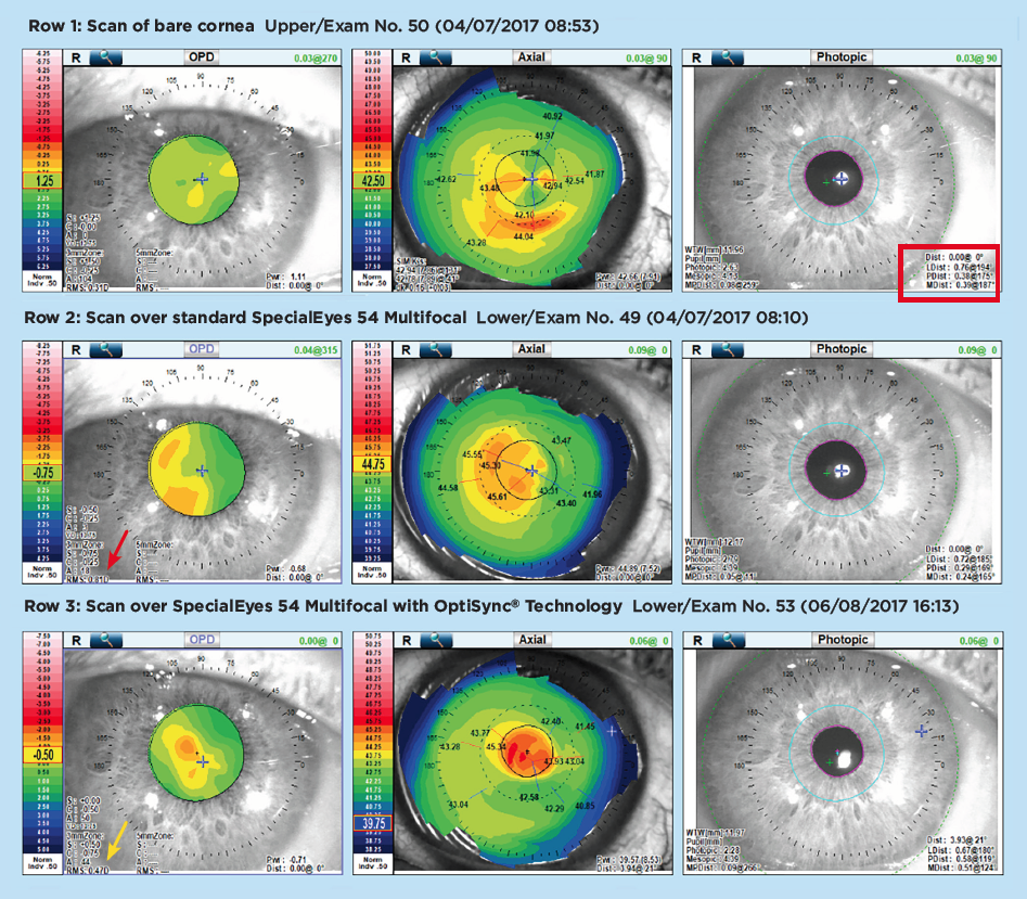
The OPD scans shown in Image 3 highlight the influence that angle alpha values can have on soft multifocal contact lenses. The top scan (Row 1) was taken with no contact lens on the eye. Notice how the angle kappa values (PDist .38mm and MDist .39mm) are borderline for predicting a multifocal misalignment issue, while the angle alpha value (LDist .76mm) predicts a significant temporal misalignment of the multifocal optics (see far right panel of Row 1). The scan in Row 2 was taken over the standard SpecialEyes 54 Multifocal design. Just as we predicted from the scan in Row 1, the axial topography map in the center panel of Row 2 demonstrates a temporal misalignment. Additionally, the root mean square (RMS) value of .81D (see far left panel of Row 2) confirms that this lens would not—and did not—provide adequate acuity. The scan in Row 3 was taken over a SpecialEyes 54 Multifocal with OptiSync® Technology, which was designed to compensate for the misalignment. As you can see in the center panel of Row 3, the axial topography shows the optics centered perfectly over the photopic pupil and optical axis. Furthermore, the OPD wavefront scan shows an acceptable RMS value of .47D (see far left panel of Row 3), with good acuity as a result.
By integrating topography, wavefront aberrometry, and pupillometry in one instrument and centering the results on the optical axis, we can assess the actual physiological alignment of the optical elements in the eye, locate aberrations (low or high order) in the optical pathway, and understand the effects of pupil size on the optical performance of the system. With this greater understanding, we can quickly determine who would benefit from which type of lenses during the diagnostic examination, and then quickly assess the performance of the lenses we choose during the contact lens evaluation.
Note: If you have specific questions on how to perform these functions with your topographer or wavefront device, please contact the device manufacturer for assistance.
Method #3: Clinical Intuition
If you don’t have a topographer or wavefront device in your office, the first step to identifying a potential misalignment is to assess the patient’s chief visual complaints in his or her current multifocal lens design. Complaints associated with a multifocal misalignment include:
- Poor near vision in a near-center lens design
- Poor distance vision in a distance-center lens design
- Shadows
- 3-D or doubled vision
- Flare/glare/halos
- Head tilt or turn improves vision
- Changing gaze direction improves vision
Once you have identified the symptoms, the next steps are to rule out any other underlying causes of poor vision. If all of the considerations below are ruled out, contact the SpecialEyes consultation department for assistance in ordering a multifocal design with offset optics.
- First, make sure the lenses provide an optimal fit and good comfort.
- Next, make sure you have a solid refraction at distance and near and have incorporated those powers into the lens design.
- Finally, evaluate your patient’s pupil size in regular room illumination. If the patient has smaller- or larger-than-average pupils, you may want to consider starting with one of our pupil-optimized designs without OptiSync® Technology first.

References
1 Lampa, Matthew; Kelvin So; et al. “Assessing Soft Multifocal Contact Lens Centration With the Aid of Corneal Topography.” Poster presented at the Global Specialty Lens Symposium; 2013.
2 SpecialEyes, LLC. Compiled from internal data; 2016–2018. Data on file.
3 Park, Choul Yong; Sei Yeul Oh; and Roy S. Chuck. “Measurement of Angle Kappa and Centration in Refractive Surgery.” Current Opinion in Ophthalmology, vol. 23, no. 4; 2012; pp. 269–275.
4 Moshirfar, Majid; Ryann Hoggan; and Valliammai Muthappan. "Angle Kappa and Its Importance in Refractive Surgery." Oman Journal of Ophthalmology, vol. 6, no. 3; 2013; pp. 151–157.
5 Prakash, Gaurav; Amar Agarwal; et al. “Role of Angle Kappa in Patient Dissatisfaction With Refractive-Design Multifocal Intraocular Lenses.” Journal of Cataract Refractive Surgery, vol. 37, no. 9; 2011; pp. 1739–1740.
6 Chan, Colin C.K. and Brian S. Boxer Wachler. “Centration Analysis of Ablation Over the Coaxial Corneal Light Reflex for Hyperopic LASIK.” Journal of Refractive Surgery, vol. 22, no. 5; 2006; pp. 467–471.