In today’s post, we’re covering how to use the Marco/NIDEK OPD-Scan III to enhance the success of your SpecialEyes soft multifocal contact lens fittings. What makes this device so unique is that it has both corneal topography and wavefront capabilities. From a consultation perspective, this gives us a range of data points to determine the best candidates for our design, as well as the ability to customize every aspect of our lenses. Ultimately, this allows us to design lenses with the greatest potential for success.
Which OPD III maps are best for designing SpecialEyes’ 54 Multifocal design?
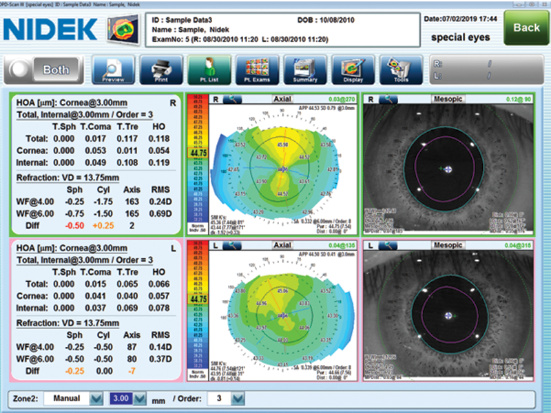
Considering all of the OPD III maps and features, you are probably wondering which ones are most useful for designing a SpecialEyes Multifocal lens. For our purposes, we find the wavefront and refractive data, axial topography map, and Mesopic Eye Image to be the most helpful. For your convenience, we have set up a default display setting that automatically pulls these three options into one SpecialEyes map (Image 1). Contact your Marco representative to gain access to this setting.
Image 1: SpecialEyes OPD Map
Accurate Refractive Data
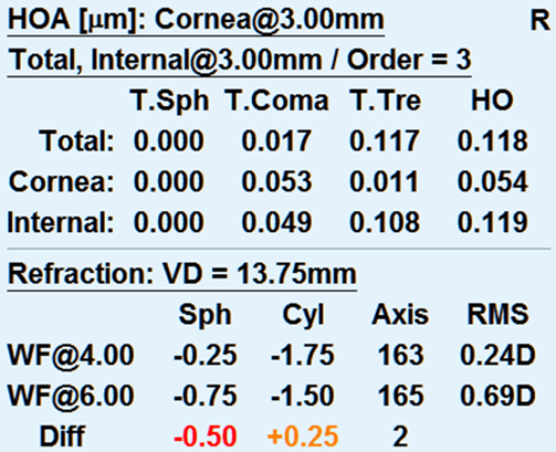
The OPD III makes evaluating a patient’s visual system extraordinarily easy. This device provides the best prescription starting point with its autorefractor and wavefront refraction features. When comparing the autorefractive data to the wavefront refractive data, be on the lookout for more than .50D of difference between the sphere and cylinder and more than a 10-degree difference in the axis (Image 2). This may indicate that the patient will be unable to obtain 20/20 vision due to higher-order aberrations.
You can verify this assumption by examining the Root Mean Square (RMS) Value. This value defines the patient’s visual potential relative to their optical system. The higher the RMS value, the worse the patient will see—despite your best refractive efforts. According to the experts at Marco, if the RMS value is higher than .43 at the 3mm zone, High-Order Aberrations are influencing the visual system and the patient may not be able to achieve good vision in a multifocal contact lens.
Furthermore, you can determine whether the type of aberration is spherical, coma, or trefoil. Spherical aberrations usually cause contrast issues, coma produces double-vision or flare, and trefoil results in three ghost-like images. In multifocal contact lenses, the ideal candidate will have .40 microns or less of spherical aberration and .32 microns or less of coma. Trefoil is almost always a lenticular/internal aberration and becomes harder to correct above .50 microns.
Image 2: OPD III wavefront and autorefractive data
Autokeratometry & Corneal Topography
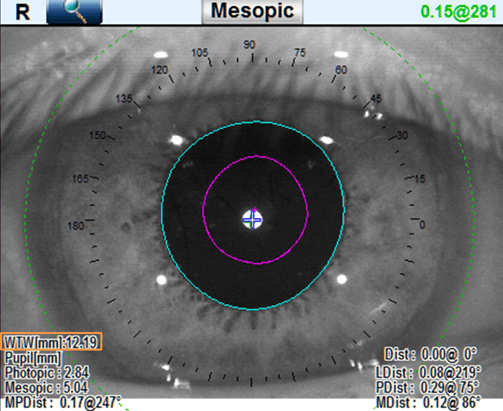
At SpecialEyes, we recognize that one size does not fit all. The OPD III provides quick and accurate keratometry readings, along with white-to-white (WTW) corneal diameter readings (Image 3). These measurements are crucial to a custom-designed soft contact lens. Utilizing these measurements with our Arc Length Calculator, SpecialEyes can design the ideal base curve and diameter for the unique shape of your patient’s eye. Additionally, these devices can quickly identify areas of irregularity that may indicate the presence of pathology such as keratoconus or pellucid marginal degeneration (PMD).
Image 3: Mesopic Eye Image map with WTW measurement
Pupil Size
Before fitting the 54 Multifocal contact lens, SpecialEyes strongly advises eye-care professionals to accurately measure the patient’s pupil size. The SpecialEyes Multifocal Simulator has the unique ability to customize the size of both the central and peripheral multifocal optic zones to ensure appropriate distribution of the multifocal optics over the pupil. The multifocal optic zones are designed to provide a good balance of vision within the setting the patient would most frequently wear the lenses. Fortunately, the OPD III makes gathering this data easier than ever by automatically measuring pupil size in both photopic and mesopic conditions.
Angle Kappa and Angle Alpha
Ensuring appropriate optical alignment between the multifocal optics and a patient’s visual and optical axes is a critical—yet often overlooked—aspect of multifocal contact lens fittings. When a misalignment is present, it can result in poor visual acuity, induced aberrations, and subjective complaints of glare, shadows, 3-D effects, and halos. Fortunately, with the innovation of OptiSync® Technology, SpecialEyes has the ability to improve these visual symptoms by offsetting the optics and improving alignment. We have found that examining a patient’s angle kappa and angle alpha are great ways to predict a potential misalignment issue.
Angle kappa is defined as the angular distance between the visual axis and the pupillary axis. Similar to multifocal intraocular lenses (IOLs), when multifocal contact-lens patients have a small angle kappa, light can travel through the center of the lens to the fovea to provide balanced vision. However, when patients have a large angle kappa, a fovea-centric light ray may pass through the edge of a multifocal zone and cause reduced vision and photic phenomena, such as halos and 3-D effects.
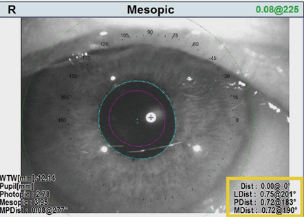
The OPD III aligns itself for topographic and wavefront measurements by finding the longest light ray, which is used to estimate the location of the visual axis. According to the NIDEK OPD-Scan III Operator’s Manual, the device then automatically calculates the distance and angle from the alignment light to the pupil center in both photopic and mesopic conditions (Image 4). These values are displayed on the map as PDist (small pink cross) and MDist (small blue cross), respectively.
The OPD-Scan III integrated wavefront aberrometer can also calculate angle alpha, which is the difference between the geometric center of the limbus (the anatomic center of the cornea) and the optical axis. The closer the center of the cornea (and the center of the lens) is to the optical axis, the more symmetric the combined power distribution is around the optical axis. The further the center of the lens is from the optical axis, the more asymmetric the combined power distribution is around the optical axis. It is this asymmetric power distribution around the optical axis that creates higher-order aberrations, particularly coma, which results in unwanted visual symptoms. This value is shown on the map as LDist and displayed as a small green cross (Image 4).
Image 4: Mesopic Eye Image map with angle kappa and angle alpha values
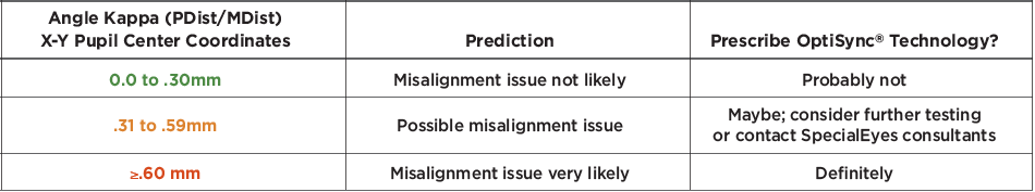
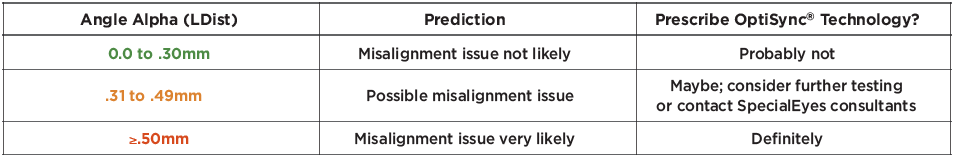
How can I use these values to determine if my patient needs OptiSync® Technology?
As previously mentioned, SpecialEyes’ OptiSync® Technology can help eliminate unwanted visual symptoms that occur with large angle kappa and angle alpha values. When evaluating these values with the OPD III, you may use the following guidelines for predicting a multifocal misalignment issue:
We hope today’s post provided some valuable insights on how to use the Marco/NIDEK OPD-Scan III to your advantage when fitting a SpecialEyes Multifocal contact lens. If you have any questions, please don’t hesitate to reach out to our consultation department or your Marco representative for more information.