How to Interpret Multifocal Simulator images for SpecialEyes' 54 Multifocal
Eye-care practitioners and educators can now use the Multifocal Simulator tool to achieve optimal outcomes for their presbyopic patients. When analyzing a simulation for the 54 Multifocal, the goal is to obtain a balance of resolution among the five images that represent distance, intermediate, and near vision across the specified add-power range. (Examples of this balance will be illustrated in the scenarios below.) It is easier to analyze a simulation across a lower add-power range than a higher range. So, as you experiment with the simulator, try selecting lower add values to start.
Scenario 1: What Does an Optimal Simulated Image Look Like? In the sample simulations below, the far-left image in each example represents full distance vision (plano), the far-right image represents full near vision (max add power), and the images in between represent intermediate vision (range of add powers). All of these simulations were calculated based on a 4.0mm pupil with a 2.0mm near-center zone and 3.5mm peripheral zone across varying add powers, and they illustrate optimal simulations for a pupil of that size.
Review each example simulation. Notice the nice balance of resolution across the specified add-power range. The key word here is balance, as opposed to a “perfect” simulation. You are aiming for a good balance between distance, intermediate, and near. Notice also as the add power increases, you can see that contrast sensitivity decreases.
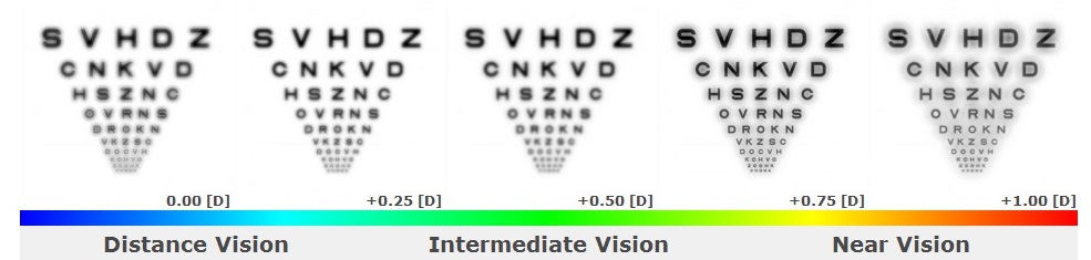
Example A: +1.00 Add
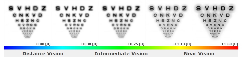
Example B: +1.50 Add
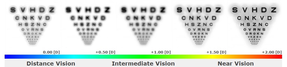
Example C: +2.00 Add
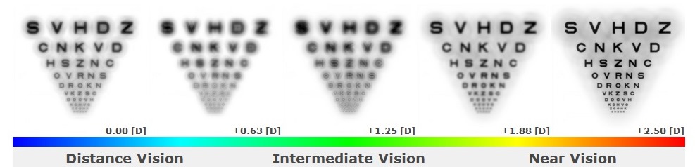
Example D: +2.50 Add
Scenario 2: The Impact of Pupil Size : Now that you understand what an optimal simulation should look like, let’s compare a standard approach to multifocal optics across two different pupil sizes. Our 54 Multifocal optics will remain constant at a 2.0mm near-center zone and a 3.5mm peripheral zone, and the add power will remain constant at +1.75 diopters. The only variable will be pupil size. Review the images below and then proceed to the interpretation.
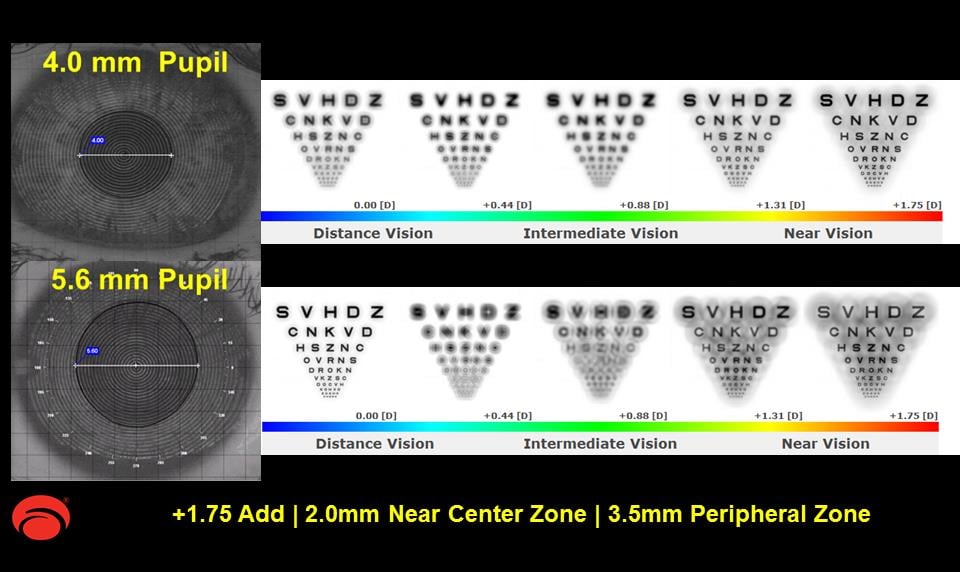
Example E
Interpretation: Upon evaluating the simulations in Example E, it is evident that there is a better balance of vision at all distances for the patient with the 4.0mm pupil than for the patient with the 5.6mm pupil when using a standard multifocal design with a 2.0mm near-center zone and a 3.5mm peripheral zone. Notice the degradation of the four images to the right in the simulation with the 5.6mm pupil; there is a definite loss of contrast and increased blur. This scenario may help explain why some of the best attempts at over-refracting never quite satisfy some multifocal patients.
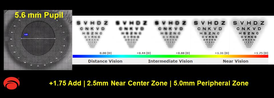
Action: Let’s redesign the 54 Multifocal optics for the patient with the 5.6mm pupil using the Multifocal Simulator. Based on a 5.6mm pupil and +1.75 add power, the 54 Multifocal design will now have a 2.5mm near-center zone and 5.0mm peripheral zone. See the corresponding simulation in Example F below. You can also access the online Multifocal Simulator and run this scenario through the simulator yourself. Take a moment to review Example F and compare it against the prior simulation in Example E. You will notice that Example F demonstrates a better balance of vision at all distances and better contrast when compared to the original simulation for the 5.6mm pupil using the standard multifocal design.
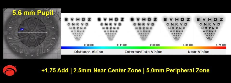
Example F
The upcoming posts feature actual case studies that will truly bring the simulator to life! In the meantime, if you find that your multifocal patient isn’t successful in a stock multifocal lens, we suggest that you evaluate the patient’s pupil size and consider trying the custom 54 Multifocal. For tips on fitting the 54 Multifocal or other products offered by SpecialEyes, please visit the online SpecialEyes Learning Center.
Until then,
The SpecialEyes Consultation Team